

Packaged Produced Water Treatment Systems: Scope, Equipment and Design Inputs

Contents
Direct answer
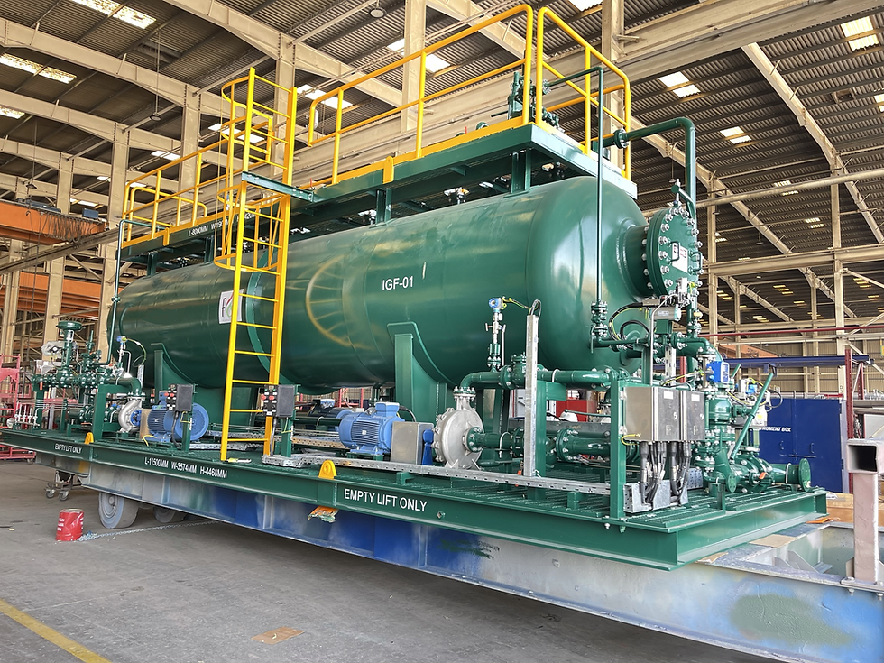
A packaged produced water treatment system should arrive as an engineered process unit, not a loose collection of vessels. A complete scope defines the contaminant-removal duty, process equipment, pumps, chemical systems, instruments, controls, piping, electrical interfaces, documentation, testing and the boundary between the supplier and the site.
The buyer should be able to trace every item back to the feed conditions, treated-water target and operating philosophy. Clear battery limits and design inputs make proposals comparable and reduce the risk of missing auxiliaries after award.
What a complete treatment package should achieve
The package specification should begin with the outcome: discharge, reinjection, reuse or further polishing. That decision governs the required oil removal, solids control, gas handling, oxygen management and chemical conditioning. The process guarantee must name the inlet envelope and the test method used to judge the outlet.
A supplier should present a process mass balance for normal, minimum, maximum and upset cases. The balance should show treated water, recovered oil, flotation skim, filter backwash, sludge, vents and drains. This prevents secondary waste streams from becoming unplanned site problems.
Core process equipment
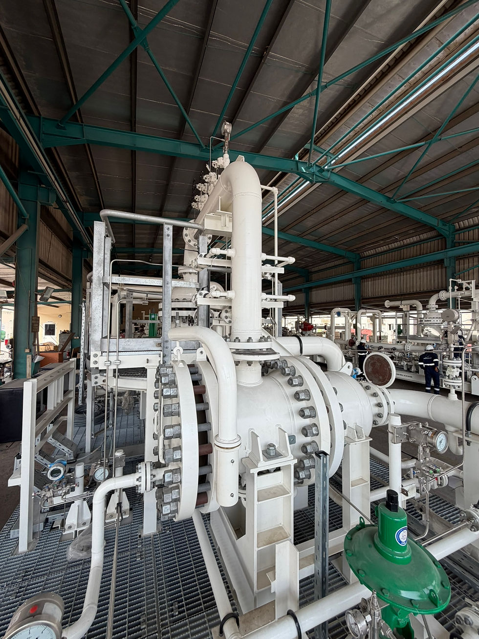
The main equipment depends on the duty. A pressurised treatment train may use deoiling hydrocyclones after upstream separation. Lower-pressure polishing may use induced gas flotation, degassing or media filtration. Reinjection duties can require fine filtration, oxygen control, biocide or scale-control facilities.
Each stage needs a defined inlet loading and removal role. The proposal should state the expected operating range, turndown, redundancy and cleaning or backwash cycle. Equipment that has no stated duty should be challenged because it adds cost and maintenance without a measurable contribution.
Pumps, chemicals and utility systems
Package scope often fails at the auxiliaries. Feed, recycle, backwash, reject and transfer pumps must be included or explicitly allocated to the client. Chemical systems may cover demulsifier, coagulant, flocculant, scale inhibitor, corrosion inhibitor, oxygen scavenger or biocide, depending on the process.
The design should state electrical power, instrument air, service water, nitrogen, fuel gas and drain requirements. Utility consumption should be shown at normal and peak conditions. Chemical storage volume, dosing range, bunding, unloading and operator exposure also belong in the design basis.
Battery limits and integration
A battery-limit schedule should identify every process, utility, electrical, control, vent and drain connection. For each connection, record size, rating, material, design conditions, termination type and responsibility. A marked-up plot plan or battery-limit diagram is more reliable than a general statement that tie-ins are by others.
The supplier also needs the available inlet pressure, downstream backpressure and elevation data. Hydrocyclone and pump selection can be undermined by an interface pressure that was assumed rather than confirmed. Brownfield projects should include tie-in surveys and the permitted shutdown window.
Instrumentation and control philosophy
A packaged system should include the measurements needed to operate and verify the process. Typical signals include flow, pressure, differential pressure, temperature, level, reject flow, chemical flow and oil-in-water performance. The proposal should distinguish local indication, transmitted signals, trips and monitoring-only values.
The control narrative should explain start-up, normal operation, low-flow response, duty and standby changeover, filter backwash, chemical interlocks and off-spec diversion. It should also define the interface with the plant DCS or PLC, communications protocol and data ownership.
Mechanical, electrical and layout scope
Skid steelwork, access platforms, lifting points, insulation, heat tracing, hazardous-area requirements and weather protection must be visible in the scope. Maintainability should be demonstrated with removal routes for liners, pumps, filters and instruments rather than left to a generic layout review.
Electrical scope may include junction boxes, local control panels, variable-speed drives, earthing, lighting and cable containment. The enquiry should state voltage, frequency, area classification and client standards. The package should not depend on an electrical item that appears nowhere in either supplier or site scope.
Documents, inspection and testing
The document register should cover calculations, process flow diagrams, piping and instrumentation diagrams, equipment datasheets, general arrangements, three-dimensional model inputs, load data, operating philosophy, cause and effect, inspection plans, manuals and spare-parts lists. Required review cycles and final formats affect schedule and cost.
The inspection and test plan should identify hold, witness and review points. Factory acceptance testing can verify fabrication records, panel logic, alarms, communications, pump rotation and functional sequences. Process guarantees normally require agreed site conditions, representative feed and an acceptance procedure.
Design inputs for a useful RFQ
A useful request for quotation supplies the flow envelope, feed analysis, oil droplet information where available, solids data, production chemicals, inlet and outlet pressures, treated-water objective, utilities, plot limits, materials standards, hazardous-area data and project schedule.
It should also define redundancy, design life, preferred manufacturers, documentation, inspection, preservation, transport, commissioning and training. When information is not yet available, mark it as an open item with an owner and required date. Hidden assumptions produce bids that look comparable but describe different packages.
Feed composition and variability
Normal, peak and future flows
Outlet target and test method
Process and utility battery limits
Redundancy and turndown
Materials and design codes
Controls and data interfaces
Documentation, FAT and commissioning
Proof to add before publication
Add a typical package-scope table, battery-limit diagram and document list using verified Crescent project information. Do not publish placeholder performance figures.
Crescent Engineering can develop the package definition from the operating envelope and site interfaces. Request a package proposal by sending the flow profile, water analysis, outlet target and project constraints.
References
Related Crescent articles
Continue exploring this topic:
Produced Water Treatment System Design: The Information Suppliers Need
Skid-Mounted Produced Water Treatment Systems for Offshore and Onshore Projects
Offshore Produced Water Treatment Packages: Footprint, Weight and Maintainability
Produced Water Reinjection Systems: Treatment Targets and Package Design

Comments